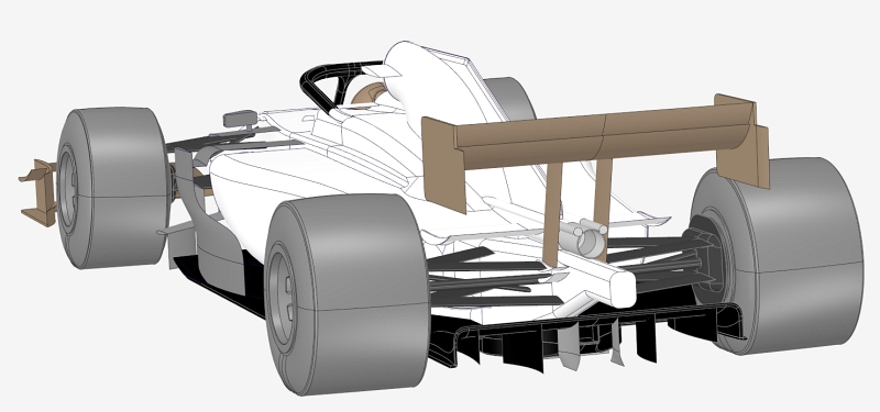
MVRC 2019 car development
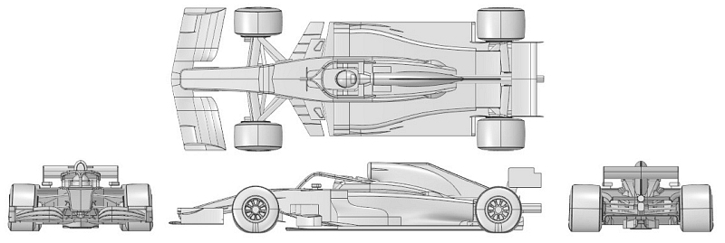
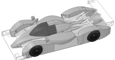
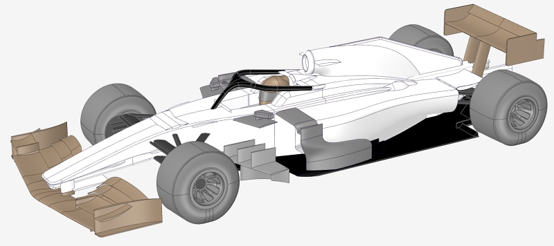
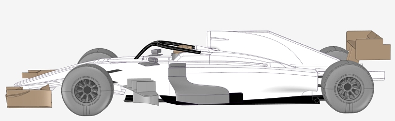
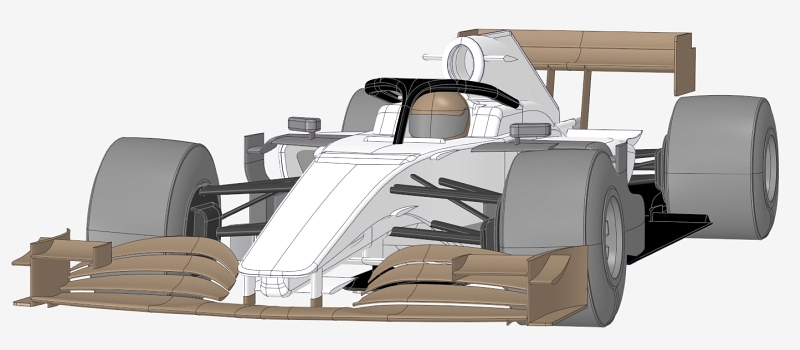
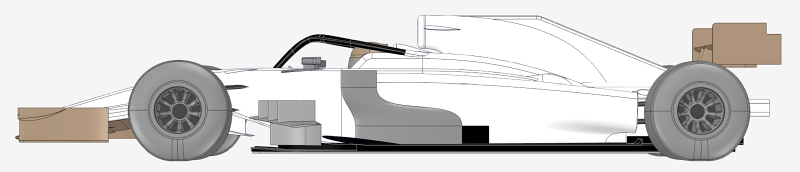
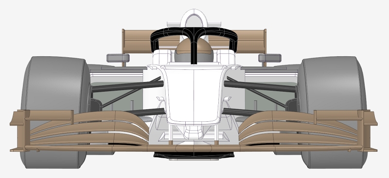
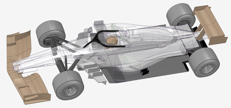
2019 MVRC season has just ended, it is time to reveal every detail of the car development. All the CFD simulation has been done with OpenFOAM, using MantiumFlow ( https://mantiumcae.com/ ) as pre/post processor. The parametric CAD modeling has been done with Solidworks.
The 3D CAD models in STEP and STEP format available here:
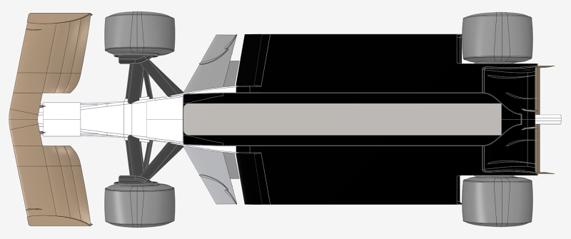
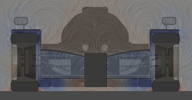
In this WordPress block I am trying to explain the reason for the hole that connects the upper part of the bottom with the diffuser. The mechanism is the reverse of the famous “double diffuser” because air is added (and not removed) from inside the diffuser. The intent is to clean the turbulent flow (due to a too abrupt transition imposed by the MVRC rules, different from F1 rules in this area). The mechanism is similar to that of the tangential flow that passes from the high pressure zone to the low pressure zone of a wing profile composed of several airfoils . The gain is small, but it can help: Cl*A + 3% Cd*A – 1%. With the layout of MP007 cooling system there is also a very small but welcome increase in flow, because the diffuser sucks air in the air outlet area.
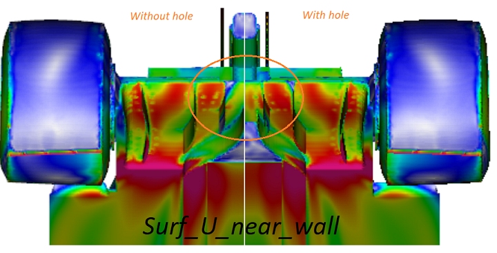
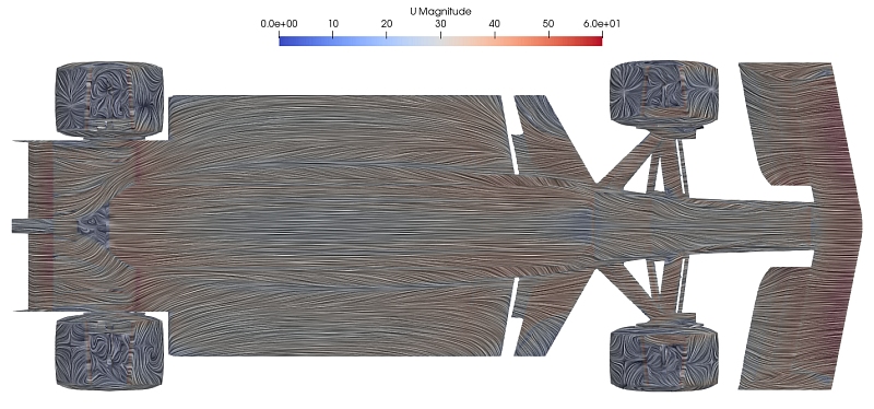
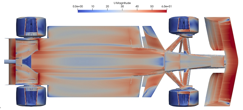
Here are the images of the “new wall velocity”.
The article is a work in progress, more images and technical data will be published in the next weeks. Please note that MVRC rules are inspired by FIA rules for F1® cars, but they are different and indipendent.